- 您现在的位置:买卖IC网 > Sheet目录39246 > LM2576D2TR4-12 (ON SEMICONDUCTOR) 7.5 A SWITCHING REGULATOR, 63 kHz SWITCHING FREQ-MAX, PSSO5
LM2576
http://onsemi.com
21
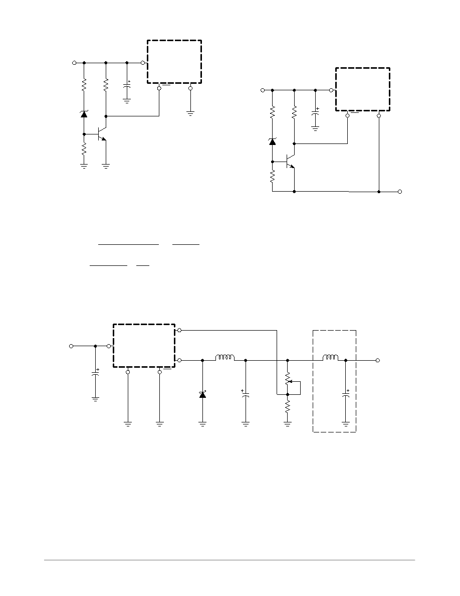
Figure 32. Undervoltage Lockout Circuit for
Buck Converter
R2
10 k
Z1
1N5242B
R1
10 k
Q1
2N3904
R3
47 k
Vth ≈ 13 V
Cin
100
mF
LM2576XX
1
3
5GN
D
ON/OFF
+Vin
NOTE: This picture does not show the complete circuit.
The following formula is used to obtain the peak inductor
current:
where ton +
|V
O
|
V
in )
|V
O
|
x
1.0
fosc
, and fosc + 52 kHz.
I
peak [
I
Load
(V
in )
|V
O
|)
V
in
)
V
in
xton
2L
1
Under normal continuous inductor current operating
conditions, the worst case occurs when Vin is minimal.
Figure 33. Undervoltage Lockout Circuit for
BuckBoost Converter
R2
15 k
Z1
1N5242B
R1
15 k
Q1
2N3904
R3
47 k
Vth ≈ 13 V
Cin
100
mF
LM2576XX
1
3
5GN
D
ON/OFF
+Vin
Vout
NOTE: This picture does not show the complete circuit.
Adjustable Output, LowRipple Power Supply
A 3.0 A output current capability power supply that
features an adjustable output voltage is shown in Figure 34.
This regulator delivers 3.0 A into 1.2 V to 35 V output.
The input voltage ranges from roughly 3.0 V to 40 V. In order
to achieve a 10 or more times reduction of output ripple, an
additional LC filter is included in this circuit.
Figure 34. 1.2 to 35 V Adjustable 3.0 A Power Supply with Low Output Ripple
D1
1N5822
L1
150
mH
Output
2
4
Feedback
R2
50 k
R1
1.21 k
L2
20
mH
Output
Voltage
1.2 to 35 V @ 3.0 A
Optional Output
Ripple Filter
40 V Max
Unregulated
DC Input
Cout
2200
mF
C1
100
mF
Cin
100
mF
LM2574Adj
1
5
3ON/OFF
GN
D
+Vin
发布紧急采购,3分钟左右您将得到回复。
相关PDF资料
LM2576TV-12G
7.5 A SWITCHING REGULATOR, 63 kHz SWITCHING FREQ-MAX, PZFM5
LM2596-12MWC
7.5 A SWITCHING REGULATOR, 173 kHz SWITCHING FREQ-MAX, UUC
LM2596-ADJMWC
7.5 A SWITCHING REGULATOR, 173 kHz SWITCHING FREQ-MAX, UUC
LM2596-ADJMDC
7.5 A SWITCHING REGULATOR, 173 kHz SWITCHING FREQ-MAX, UUC
LM2601MDC
1-CHANNEL POWER SUPPLY SUPPORT CKT, UUC
LM2601MWC
1-CHANNEL POWER SUPPLY SUPPORT CKT, UUC
LM2636MTC/NOPB
SWITCHING CONTROLLER, 2000 kHz SWITCHING FREQ-MAX, PDSO20
LM2636M/NOPB
SWITCHING CONTROLLER, 2000 kHz SWITCHING FREQ-MAX, PDSO20
相关代理商/技术参数
LM2576D2TR4-3.3
功能描述:直流/直流开关调节器 3.3V 3A Buck PWM RoHS:否 制造商:International Rectifier 最大输入电压:21 V 开关频率:1.5 MHz 输出电压:0.5 V to 0.86 V 输出电流:4 A 输出端数量: 最大工作温度: 安装风格:SMD/SMT 封装 / 箱体:PQFN 4 x 5
LM2576D2TR4-3.3G
功能描述:直流/直流开关调节器 3.3V 3A Buck PWM RoHS:否 制造商:International Rectifier 最大输入电压:21 V 开关频率:1.5 MHz 输出电压:0.5 V to 0.86 V 输出电流:4 A 输出端数量: 最大工作温度: 安装风格:SMD/SMT 封装 / 箱体:PQFN 4 x 5
LM2576D2TR4-3.3G-CUT TAPE
制造商:ON 功能描述:LM2576 Series 40 V 3 A 52 kHz Step-Down Switching Regulator - D2PAK-5
LM2576D2TR4-5G
功能描述:直流/直流开关调节器 5V 3A Buck PWM RoHS:否 制造商:International Rectifier 最大输入电压:21 V 开关频率:1.5 MHz 输出电压:0.5 V to 0.86 V 输出电流:4 A 输出端数量: 最大工作温度: 安装风格:SMD/SMT 封装 / 箱体:PQFN 4 x 5
LM2576DP-12
制造商:HTC 制造商全称:HTC Korea TAEJIN Technology Co. 功能描述:3A, 52kHz, Step-Down Switching Regulator
LM2576DP-3.3
制造商:HTC 制造商全称:HTC Korea TAEJIN Technology Co. 功能描述:3A, 52kHz, Step-Down Switching Regulator
LM2576DP-5.0
制造商:HTC 制造商全称:HTC Korea TAEJIN Technology Co. 功能描述:3A, 52kHz, Step-Down Switching Regulator
LM2576DP-ADJ
制造商:HTC 制造商全称:HTC Korea TAEJIN Technology Co. 功能描述:3A, 52kHz, Step-Down Switching Regulator